Model-Based Design to Develop and Deploy a
Video Processing Application
04 Implementing and Verifying the Application on TI Hardware
Using Real-Time Workshop® and Real-Time Workshop Embedded Coder, we automatically generate code and implement our embedded video application on a TI C6400™ processor using the Embedded Target for TI C6000™ DSP. To verify that the implementation meets the original system specifications, we can use Link for Code Composer Studio™ to perform real-time "Processor-in-the-Loop" validation and visualization of the embedded application.
Before implementing our design on a TI C6416DSK evaluation board, we must convert the fixed-point, target-independent model to a target-specific model. For this task we use TCP/IP Send and Receive a TI real-time communications protocol that enables the transfer of data to and from the host.
Creating the target-specific model involves three steps:
Replace the source block of the target-independent model with the "TCP/IP Receive" block and set its parameters.
Replace the Video Viewer block of the target-independent model with the "TCP/IP Send" block and set its parameters.
Set up Real-Time Workshop target-specific preferences by dragging a block specific to our target board from the C6000 Target Preferences from Target Support Package library into the model.


Figure 7: Target-Specific Model.
To automate the process of building the application and verifying accurate real-time behaviour on the hardware, we can create a script, using Link for Code Composer Studio to perform the following tasks:
Invoke the Link for Code Composer Studio IDE to automatically generate the Link for Code Composer Studio project.
Compile and link the generated code from the model.
Load the code onto the target.
Run the code: Send the video signal to the target-specific model from the same input file used in simulation and retrieve the processed video output from the DSP.
Plot and visualize the results in a MATLAB figure window.
Here is the Figure 8, shows the script used to automate embedded software verification for TI DSPs from MATLAB. Link for Code Composer Studio provides several functions that can be invoked from MATLAB to parameterize and automate the test scripts for embedded software verification.
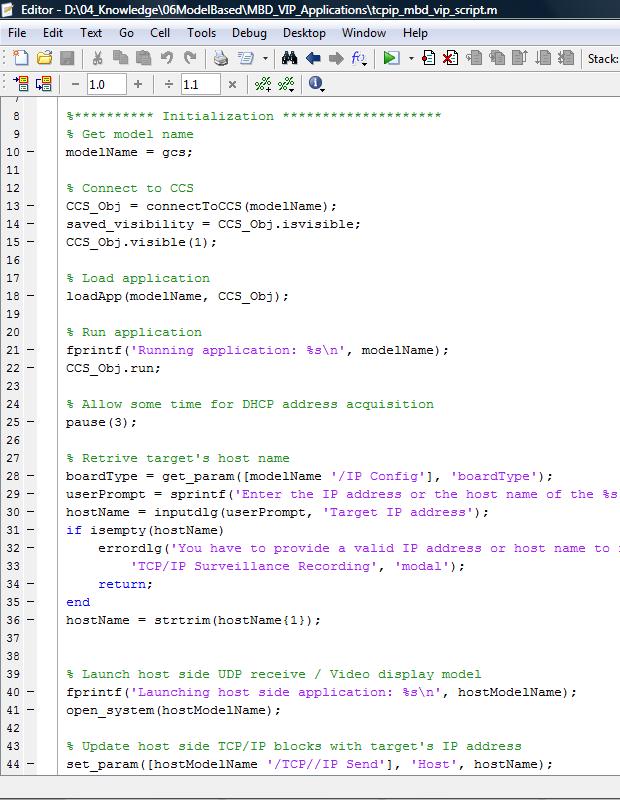
Figure 9 shows the results of the automatically generated code executing on the target DSP. Means, you can observe that the application running on the target hardware properly, and verify that the application meets the requirements of the original model.
Figure 9: Result of the Automatically Generated Code Executing on the Target DSP
After running the application on the target, we may find that algorithm does not meet the real-time hardware requirements. In Model-Based Design, simulation and code generation are based on the same model, and so we can quickly conduct multiple iterations to optimize the design. For example, we can use the profiling capabilities in Link for Code Composer Studio to identify the most computation-intensive segments of our algorithm. Based on this analysis, we can change the model parameters, use a more efficient algorithm, or even replace the general-purpose blocks used in the model with target-optimized blocks supplied with the Embedded Target for TI C6000. Such design iterations help us optimize our application for the best deployment on the hardware target.
This demo is configured to run in an Ethernet network where there is a DHCP server. A DHCP server allows automatic assignment of the IP parameters of the target board. During this process, the status of the Ethernet link as well as the acquired IP address is displayed on the standard output window of the CCS IDE. If you don't have a DHCP server in your network, you must manually configure the IP parameters on the target side model. In order to do this, open the C6000™ IP Config block in the target side model, uncheck Use DHCP to allocate an IP address option and manually enter Use the following IP address, Subnet mask, Gateway IP, Domain name server IP address and Domain name parameters. You must always set Use the following IP address and Subnet mask parameters to meaningful values. As a rule of thumb, leave the Subnet mask parameter at its default value of "255.255.255.0" and set Use the following IP address parameter so that the first three numbers in the IP address assigned to the target board matches to those found in your computer's IP address. For example, if your computer's IP address is "100.101.102.3" you may choose "100.101.102.4" to be assigned to the target board provided that there is no other Ethernet device using IP address "100.101.102.4". Make sure that there are no IP address collisions when assigning an IP address to the target board. If you are unsure about what to enter for any other IP parameter, leave it at its default value.


No comments:
Post a Comment
Note: Only a member of this blog may post a comment.